Difference between revisions of "OroboPOS-Connector"
| Line 1: | Line 1: | ||
{{Product | {{Product | ||
|description='''OroboPOS-Connector''', with male connection to [[OroboPOS]] sensor head (POS) and with cable and male plug fitting into [[O2k-Main Unit]]. | |description='''OroboPOS-Connector''' (blue POM), with male connection to [[OroboPOS]] sensor head (POS) and with cable and male plug fitting into [[O2k-Main Unit]]. | ||
[[O2k-Core]]: 2 in [[O2k-Assembly Kit]], mounted on the [[OroboPOS-Holder]]s at the [[O2k-Main Unit]]. | [[O2k-Core]]: 2 in [[O2k-Assembly Kit]], mounted on the [[OroboPOS-Holder]]s at the [[O2k-Main Unit]]. | ||
Revision as of 10:21, 22 January 2013

![]()


OroboPOS-Connector

| Description | OroboPOS-Connector (blue POM), with male connection to OroboPOS sensor head (POS) and with cable and male plug fitting into O2k-Main Unit.
O2k-Core: 2 in O2k-Assembly Kit, mounted on the OroboPOS-Holders at the O2k-Main Unit. |
|---|---|
| Product ID | 22200-01 |
| Type | O2k, O2k-Assembly Kit, OroboPOS |
| Link | Previous Product ID #25000-34, O2k-Assembly Kit, O2k-Manual @OROBOROS |
| Image | 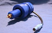 |
The two electronic connections of the POS connector (to the POS and to the Main unit) make a POS connector that has been disconnected from the POS or from the Main unit or from both particular sensitive to damage by ESD. Therefore it is of special importance to follow the guidelines for ESD protection [MiPNet14.1] whenever handling a POS connector.
Functions
The POS connector has several different functions:
- It mechanically presses the POS against the glass chamber, ensuring a tight fit.
- It connects the POS electronically to the main unit transmitting the signal.
- In O2k Series A-C it also performs the current to voltage conversion / amplification. For Series D and upwards this function has been incorporated into the Main unit. For this reason POS connectors for Series A-C and for Series D are NOT interchangeable.
Possible Problems
Nearly all problems usually associated with the POS may in fact be caused by the POS connectors, e.g.
- unstable O2 signal
- unstable O2 flux
- high O2 signal at air saturation
- high O2 signal at zero oxygen
Performing the Sensor Test
Confirm the problem by doing a Sensor test in the absence of biological material
Option 1.A: No problem was visible in the Sensor test
check the following DatLab settings
- Gain (O2 channel)
- POS calibration
- Scaling
If the problem is not visible when observing the Raw signal but is visible when observing the calibrated oxygen signal, then there is probable a problem with the POS calibration.
Option 1.B: The problem was visible in the Sensor test
- proceed to Localizing the Problem
Localizing the Problem
Option 2.A: The problem was localized on the POS connector
Solutions 2.A Follow the instructions for cleaning and applying contact oil as described in the sensor service manual [MiPNet08.04] and in more detail at Cleaning the POS connector. If you have also done a Sensor service or changed the POS membranes allow the oxygraph to run over night before repeating the Sensor test. If all service precautions fail to solve the problem, or a new POS connector has to be applied.
Option 2.B: The problem was not localized on the POS connector
Solutions 2.B If the problem was localized on an other component follow the instructions for this component. If you could not locate the problem contact OROBOROS Instruments.