Difference between revisions of "O2k-Open Support"
| Line 65: | Line 65: | ||
* '''Application problems''' | * '''Application problems''' | ||
:: An '''application problem''' can be diagnosed on the basis of O2k-calibration and instrumental background tests performed in | :: An '''application problem''' can be diagnosed on the basis of O2k-calibration and instrumental background tests performed in incubation medium in the absence of an experimental sample. Analysis of DatLab files recorded in such instrumental tests is essential. If proper instrumental performance is obtained, software and hardware problems are excluded. | ||
* '''Software problems''' | * '''Software problems''' | ||
| Line 90: | Line 90: | ||
* The O2 sensor test is not only required to evaluate the function of the OroboPOS. To obtain a high-resolution oxygen signal, many other components of the O2k have to function according to specifications. Examples for parts that may be not properly handled, assembled or be defective, and which may explain problems observed at the level of an O2 sensor test: | * The O2 sensor test is not only required to evaluate the function of the OroboPOS. To obtain a high-resolution oxygen signal, many other components of the O2k have to function according to specifications. Examples for parts that may be not properly handled, assembled or be defective, and which may explain problems observed at the level of an O2 sensor test: | ||
# [[DatLab]] not operated properly. | # [[DatLab]] not operated properly. | ||
## Check [[Scaling]]. | ## Check [[Scaling]]. | ||
## Check the | ## Check settings for [[Gain]] (use Gain 1) and [[Polarization voltage]] (use 800 mV). | ||
## If the signal remains off scale (9.99 V) or very low (< 1 V) at air saturation and 37 °C, many components may be responsible, and an electronic defect of the [[Main unit]] must be carefully excluded. | |||
## Empty the chamber with the O2k running and connected to DatLab. Switch the stirrer off. Remove the [[OroboPOS connector]] with the attached [[OroboPOS]]. Leave the sensor attached to the POS connector, and the POS connector plugged into the O2k-Main Unit. Set an event and record the signal for a short time (some min). The raw signal should normalize to a value >1 V and < 3 V (Gain 1). If so, the O2k-Chamber assembly was problematic (application problem). If not, the OroboPOS must be serviced, to exclude a hardware problem of the sensor. | |||
## Remove the sensor head from the sensor connector, which remains plugged into the O2k-Main Unit. The raw signal should be stable at 0 V. If so, the OroboPOS must be serviced, to exclude a hardware problem of the sensor. If not, a defect of the [[OroboPOS-Connector]] is indicated. | |||
## Remove the plug of the [[OroboPOS connector]] from the [[O2k-Main unit]]. For O2k-Series D and higher: typically 0 V; for O2k-Series A to C: the typical signal is off-scale (+/- 9.99 V). A gain-independent stable signal of 0.4 V is a strong indication of an electronic problem in the O2k-Main unit. | |||
# [[USB-Cable 2.0\Type A-B]] not properly connected to the O2k and PC or Laptop. | # [[USB-Cable 2.0\Type A-B]] not properly connected to the O2k and PC or Laptop. | ||
# [[O2k-Chamber]] not properly positioned, such that O2 sensors are not connected to the medium. | # [[O2k-Chamber]] not properly positioned, such that O2 sensors are not connected to the medium. | ||
| Line 113: | Line 116: | ||
# If the problem remained on the same side, switch the [[POS connector]] together with the attached sensors between right and left side (A and B). | # If the problem remained on the same side, switch the [[POS connector]] together with the attached sensors between right and left side (A and B). | ||
# Repeat the O2 sensor test. If the problem moved together with the POS connector, it is located at the [[POS connector]]. | # Repeat the O2 sensor test. If the problem moved together with the POS connector, it is located at the [[POS connector]]. | ||
# An electronic defect in the [[Main unit]] can be detected at the level of the O2 sensor test. This should be confirmed by removing components as described below. | |||
| Line 142: | Line 146: | ||
# Perform an O2 sensor test and - if successful - an O2k-chamber test. | # Perform an O2 sensor test and - if successful - an O2k-chamber test. | ||
# If the problem with the instrumental O2 background remains in the same chamber, switch sensors between the left and right chamber. | # If the problem with the instrumental O2 background remains in the same chamber, switch sensors between the left and right chamber. | ||
Revision as of 19:38, 7 February 2016
O2k-Open Support
- - we provide service and support based on open innovation
MitoPedia
Find information quickly with MitoPedia, the Bioblast glossary with lists of key words and links to relevant pages, specifically and the O2k and high-resolution respirometry:
O2k-Protocols
O2k-Protocols explain various applications of the O2k with O2k-Demo experiments, SOPs beyond the O2k-Manual, and more: » O2k-Protocols
- Implement your quality control management with the MitoFit QCS, to diagnose technical problems fast and cost-effectively with instrumental quality control tests.
- » O2k-standard operating procedures: » O2k-SOP
- » Polarographic oxygen sensors: calibration, accuracy and quality control SOP. » MiPNet06.03 POS-Calibration-SOP
- » Instrumental background correction, accuracy of oxygen flux and SOP. » MiPNet14.06 InstrumentalO2Background
O2k-Manual
The O2k-Manual helps beginners and experienced users. Find technical information and instructions in the main sections (Bioblast pdf files), complemented by details on specific webpages: » O2k-Manual
O2k-Videosupport
O2k-Catalogue
The O2k-Catalogue is a guided tour through the O2k technology, with links to specific sections of the O2k-Manual, and more: » OROBOROS O2k-Catalogue
Open innovation
- Open innovation extends the support given to individual users to the scientific community and provides feedback to improve the scope and documentation of the O2k-technology - in the spirit of Gentle Science.
- We welcome and value feedback. Technical and scientific questions, which are not yet addressed in the available guidelines or are difficult to trace on our website, will be relevant to both specialists and beginners in the field.
- Expansion of O2k-SOPs is particularly relevant for novel approaches in O2k-Fluorometry and O2k-Spectrophotometry, which are combined in the development of the NextGen-O2k.
- Extended O2k-technical support
- O2k-technical support is defined as extended if support is requested on O2k-technology and high-resolution respirometry without prior consulting the O2k-Manual and relevant chapters on O2k-Protocols.
- Regular consultancy fees apply for extended O2k-technical support requested without open innovation agreement.
- Acceptance of extended O2k-technical support with an open innovation agreement implies that OROBOROS INSTRUMENTS may publish the relevant correspondence or a summary of the correspondence addressing technical and scientific questions on our website, including names, institutional and Email addresses.
O2k-technical support
- Application problems
- An application problem can be diagnosed on the basis of O2k-calibration and instrumental background tests performed in incubation medium in the absence of an experimental sample. Analysis of DatLab files recorded in such instrumental tests is essential. If proper instrumental performance is obtained, software and hardware problems are excluded.
- Software problems
- Communication between the O2k and DatLab running on a computer.
- Hardware problems
- Diagnostic tests are available to identify a defective instrumental component. The two-chamber design of the O2k provides the option to exchange parts between the two chambers and thus locate a defective component.
- Hardware problems that can be solved by user-service: The OroboPOS (polarographic oxygen sensor) requires user-service at intervals (these may be more than 1 year), and SOPs are available to determine if a sensor service is required at an earlier or later date.
- Hardware problems that require replacement of a defective part.
- Some electronic or mechanical defects may be solved only by service of the O2k in the workshop of OROBOROS INSTRUMENTS, e.g. a defective Peltier unit.
- The O2 sensor and O2k chamber tests are important to eliminate instrumental artefacts, which then can be distinguished from problems arising from solution protocols (perparation of chemicals), sample preparation protocols, and SUIT protocols. Biological experiments are not suitable for trouble shooting. Clean O2k-Chambers and contamination-free incubation medium are required. The sequence of quality control tests is strictly
- O2 sensor test
- O2 chamber test
- The two chamber design of the O2k has many benefits, including advantages in trouble shooting. By switching components between sides A and B of the O2k, it is usually possible to locate an instrumental problem, finding selectively a specific defective component of the O2k. This component can then be serviced by the end user or replaced by OROBOROS without the need to ship the entire O2k.
O2 sensor test
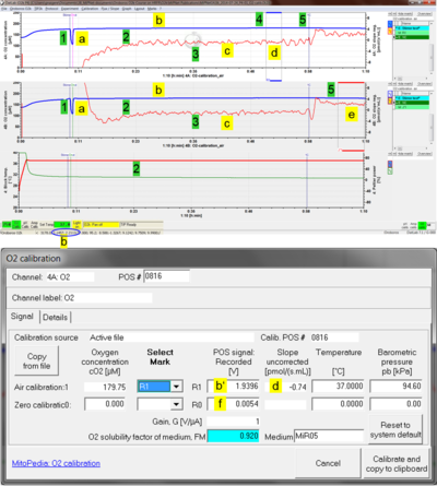
Many technical problems of O2k-Core applications can be analyzed and solved with the O2 sensor test, described in detail as an O2k-SOP:
- » O2 sensor test: MiPNet06.03 POS-Calibration-SOP
- The O2 sensor test is not only required to evaluate the function of the OroboPOS. To obtain a high-resolution oxygen signal, many other components of the O2k have to function according to specifications. Examples for parts that may be not properly handled, assembled or be defective, and which may explain problems observed at the level of an O2 sensor test:
- DatLab not operated properly.
- Check Scaling.
- Check settings for Gain (use Gain 1) and Polarization voltage (use 800 mV).
- If the signal remains off scale (9.99 V) or very low (< 1 V) at air saturation and 37 °C, many components may be responsible, and an electronic defect of the Main unit must be carefully excluded.
- Empty the chamber with the O2k running and connected to DatLab. Switch the stirrer off. Remove the OroboPOS connector with the attached OroboPOS. Leave the sensor attached to the POS connector, and the POS connector plugged into the O2k-Main Unit. Set an event and record the signal for a short time (some min). The raw signal should normalize to a value >1 V and < 3 V (Gain 1). If so, the O2k-Chamber assembly was problematic (application problem). If not, the OroboPOS must be serviced, to exclude a hardware problem of the sensor.
- Remove the sensor head from the sensor connector, which remains plugged into the O2k-Main Unit. The raw signal should be stable at 0 V. If so, the OroboPOS must be serviced, to exclude a hardware problem of the sensor. If not, a defect of the OroboPOS-Connector is indicated.
- Remove the plug of the OroboPOS connector from the O2k-Main unit. For O2k-Series D and higher: typically 0 V; for O2k-Series A to C: the typical signal is off-scale (+/- 9.99 V). A gain-independent stable signal of 0.4 V is a strong indication of an electronic problem in the O2k-Main unit.
- USB-Cable 2.0\Type A-B not properly connected to the O2k and PC or Laptop.
- O2k-Chamber not properly positioned, such that O2 sensors are not connected to the medium.
- OroboPOS-Membranes defective or not properly applied.
- OroboPOS-Connector contaminated gold contacts; plugs not properly connected to the sockets of the O2k-Main Unit.
- Pen-Contact Oil OroboPOS contacts not cleaned.
- OroboPOS-Electrolyte Powder contaminated, inappropriate water used for dissolving the powder.
- O2-Zero Powder not properly handled; confused with OroboPOS-Polishing Powder.
- OroboPOS not properly serviced; not properly mounted to the OroboPOS-Connector; or defective POS head.
- Room temperature not sufficiently stable.
- Stirrer-Bar\white PVDF\15x6 mm not added to the chamber, or stuck and not rotating.
- O2k-Barometric Pressure Transducer not properly calibrated.
- O2k-Peltier Temperature Control defective electronics.
- O2k-Electromagnetic Stirrer Twin-Control defective electronics.
- O2k-Main Basic not properly connected; other defective hardware.
- If a problem occurs: Stop and start trouble shooting at the level of components which secure the quality of the O2 sensor signal and O2 concentration.
- Switch the OroboPOS between O2k-Chamber A and B. This is a good opportunity to clean the gold contacts and apply Contact oil to the gold pin and thread connecting the POS connectors and sensors. It is not necessary to remove the mounted membrane and the seal tip from the OroboPOS. When disconnecting a sensor from the POS connector observe the guidelines to prevent damage by ESD (MiPNet14.01 ESD Damage).
- Repeat the O2 sensor test. If the problem moved together with the sensor from one side to the other, the problem is located in the OroboPOS sensors.
- If the problem remained on the same side, switch the POS connector together with the attached sensors between right and left side (A and B).
- Repeat the O2 sensor test. If the problem moved together with the POS connector, it is located at the POS connector.
- An electronic defect in the Main unit can be detected at the level of the O2 sensor test. This should be confirmed by removing components as described below.
O2k-chamber test
If all quality control criteria of the O2 sensor test are met, the operator can be assured that the quality of the sensor signal is acceptable. Next, the quality of the O2k-Chamber assembly has to be tested.
- » O2k chamber test: MiPNet14.06 InstrumentalO2Background
- Examples for parts that may be not properly handled, assembled or be defective, and which may explain problems observed at the level of an O2k-chamber test, but not with the O2 sensor test:
- O2k-Chamber not properly assembled or broken.
- OroboPOS-Holder not properly positioned.
- O2k-Chamber Holder not properly positioned; V- and O-rings not properly mounted (V-ring\30-35-4.5 mm, O-ring\Viton\18x2 mm).
- Volume-Calibration Ring not properly positioned by chamber volume calibration.
- O-ring\Viton\12x1 mm injured and must be replaced on the stopper.
- Stopper\black PEEK\conical Shaft\central Port broken conical edge or O-ring not properly applied.
- OroboPOS-Seal Tip leaky.
- Experimental medium consumes oxygen due to microbial contamination.
- If a problem occurs: Stop and start trouble shooting at the level of components which secure the quality of the O2 chamber and O2 flux.
- Check the stirring bars for any contamination.
- Check the stoppers for the quality of the O-rings and the conical edges.
- If no indications of a defect are observed, disassemble the O2k-Chamber.
- Check the glass chamber for contamination or for broken edges.
- Clean the copper block of the O2k and reassemble the O2k-Chamber.
- Reassemble and clean the chambers: MiPNet19.03 O2k-cleaning and ISS.
- Perform an O2 sensor test and - if successful - an O2k-chamber test, using fresh incubation medium.
- If the problem with the instrumental O2 background remains in one chamber, switch stoppers between chambers A and B.
- Perform an O2k-chamber test (the sensor test is not necessary).
- If the problem with the instrumental O2 background remains in the same chamber, switch glass chambers between the left and right side of the O2k.
- Perform an O2 sensor test and - if successful - an O2k-chamber test.
- If the problem with the instrumental O2 background remains in the same chamber, switch sensors between the left and right chamber.
The query description has an empty condition.
Cost estimation for repair
- A cost estimation for repair of the O2k-Main unit due to an electronic/mechanical defect can only be given after inspection of the O2k by our workshop in Austria. Once a cost estimation has been provided, the repair is carried out after the customer’s consent. For shipment of the O2k, follow the detailed instructions.
OROBOROS MitoFit Laboratory
- The OROBOROS MitoFit Laboratory is open for innovation and cooperation.
The O2k-Network - are you connected?
- The OROBOROS O2k-Network serves to connect and support:
- » The O2k-Network Labs: » O2k-Network.
- » Communication on a scientific level: O2k versus multiwell respirometer
- » Studies in mitochondrial physiology: » Applications.
- » OROROBOS Science Scholarships
Contact
- In case you need further technical support, contact support@oroboros.at


